A WII5 hull of the kind the WII6 electronics are designed to fit.
A WII6 buoy sits on sea ice or floats at the ice edge and measures how the
surface moves. It records motion, computes the wave statistics on board,
and sends the selected data over Iridium. The full record is written to
the card.
Capture length, sampling rate and reporting interval are configurable. A
fifteen-minute capture every two hours is one example. Reporting can be
every fifteen minutes, once a day or on another interval, and captures can
be shorter or longer to suit the deployment.
What it measures
Sensor
Measurements and purpose
Motion sensor
acceleration and orientation for the wave maths; the Sparton AHRS-M2 is an option proven on multiple WII5 deployments
GNSS
position and time from a single receiver
Heading
motion-sensor heading, with a dual-antenna GNSS model available for accurate direction near the poles
Temperature probes
air and water temperature, according to the deployment’s probe arrangement
Power monitoring
power and voltage measured on multiple buses to track the buoy’s health
What it sends
Messages can start with 326 bytes of wave results: significant wave
height, peak period, the power spectrum, direction and quality flags.
Position and buoy health can be sent alongside them.
You choose which captures send just the power spectrum, which send a 2 Hz
record, and which send the full-rate record at 8 or 64 Hz. For a
fifteen-minute capture, the 2 Hz record is about 56 kB and fits in a single
Iridium Certus message. It lets you rerun the later processing stages on
shore with different settings.
Full-rate transfers use more airtime and cost more, so the 2 Hz record is
the practical choice for most satellite reprocessing requests. The full
record remains on the card for recovery. It includes the filtering already
applied inside the motion sensor.
What changed from WII5
Feature
WII5 v2
WII6
Main processor
ATmega2560 at 11 MHz, 8 kB RAM
STM32U575, Cortex-M33 at 160 MHz, 786 kB SRAM
Wave maths
on a Raspberry Pi woken for the job
on the main processor, using SRAM
Satellite
Iridium SBD, 340 bytes a message
Iridium Certus, about 100 kB a message
Firmware
Arduino
Zephyr RTOS
Debug and local access
Raspberry Pi
ESP32-S3 with WiFi, off in deployment
Storage
two SD cards
one SD card, a write-once record layout
Power
per-peripheral switches
switched supplies, with power and voltage measured on multiple buses
The Sparton motion sensor remains an option for WII6, building on its use
in multiple WII5 deployments. Earlier generations used a Kistler
single-axis accelerometer with a lower-cost inertial measurement unit
(IMU). The heritage page traces that development.
Where it stands
The WII6 electronics are in bench bring-up on development boards: the
sensors, the card, the satellite modem and the link to the dashboard all
exercised one at a time by a hardware test suite before a board is laid
out. If you are planning a season, get in touch for the
current development schedule.
Electronics: the board, power monitoring and firmware.
Hulls and boxes: what the enclosure has to survive and the forms it takes.
Uses: where a buoy can go, and what it can be fitted to.
1 - Electronics
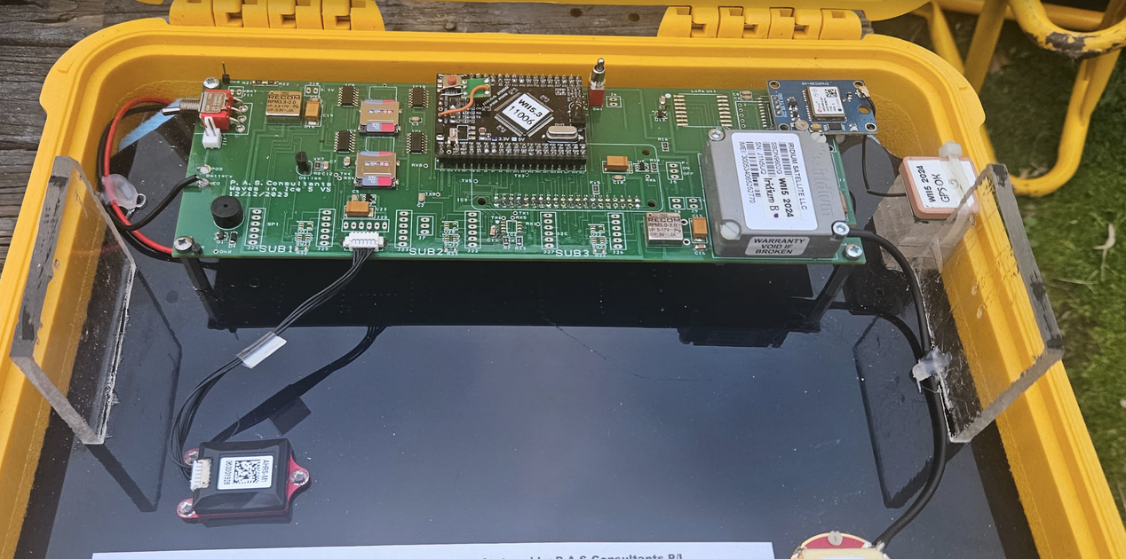
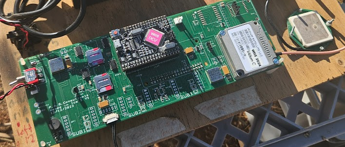
The WII6 board: an STM32U575 on Zephyr, an ESP32-S3 debug processor, Iridium Certus, and power and voltage monitoring on multiple buses.
The WII5 v2 main board. In WII6, the STM32 takes over control and wave
processing from the ATmega2560 and Raspberry Pi.
The board
Role
Part
Purpose
Main processor
STM32U575ZI
ST’s ultra-low-power line, five serial ports, 786 kB SRAM for the wave maths, Zephyr support upstream
Debug processor
ESP32-S3 on a XIAO socket
WiFi, Bluetooth and a web server, powered down during deployment
Motion
Sparton AHRS-M2 option
proven on multiple WII5 deployments
Satellite
RockBLOCK 9704, Iridium Certus
about 100 kB a message, which is what lets the 2 Hz record travel
Position
u-blox GNSS, NMEA
position and time from a single receiver; a dual-antenna model is available for accurate heading near the poles
Temperature
DS18B20 probes
temperature measurements for the deployment
Power monitoring
INA3221 and INA228
power and voltage measurements on multiple buses, plus battery monitoring
Storage
one SD card
full-rate records, 2 Hz records and wave results
Power monitoring
Power and voltage are measured on multiple buses, alongside battery
monitoring, so a deployment can track energy use and the buoy’s health.
Switched supplies let the firmware power down peripherals between jobs.
The debug processor is powered down during deployment.
Duty cycle
Capture length and reporting interval are configurable. A fifteen-minute
capture every two hours is one example; shorter captures, more frequent
reports or daily reporting can be chosen to suit the deployment.
The power budget depends on time spent sampling, processing and sending
data, as well as consumption between wake-ups. Sleep consumption matters
most when the buoy spends long periods waiting for its next capture.
Firmware
Zephyr RTOS, built with west, with the wave maths as a library that builds
and tests the same way on a workstation and on the processor. The bench
image is a hardware test suite: each peripheral exercised on its own, with
a shell for all of it and a JSON status frame once a second to the
dashboard. The maths library, the card layout and the link protocol are
documented in the engineering repository. Ask us for the documentation
if you are planning an integration.
2 - Hulls and boxes
What a WII buoy enclosure has to survive on Antarctic sea ice, and the forms it takes: the ice-surface box, the floating hull, the tethered variant.
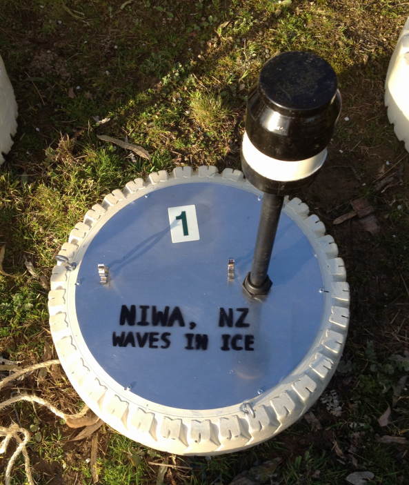
The 2012 buoy, a disc with a tyre around the rim.
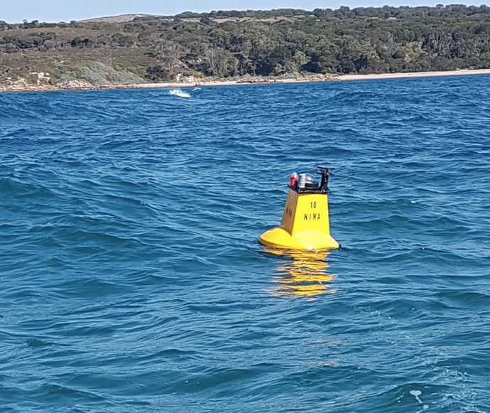
A floating hull in open water.
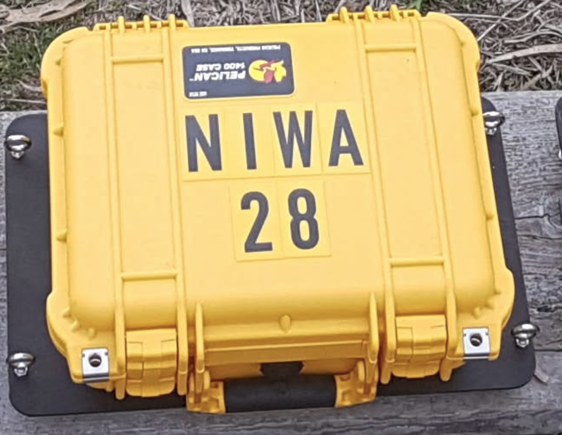
An ice-surface box, a Pelican case on a base plate.
The enclosure drives almost everything downstream: battery size, sensor
mounting, what the antenna can see, and how the buoy behaves when the ice
moves. WII6 is designed to fit the hulls that carried WII5, and the same
rules apply.
Ice survival
The enclosure lives on or in sea ice for months: freeze-in, freeze-thaw
cycles, ridging, and the loads when floes collide.
Sealing under thermal cycling. Gaskets that work in a warm workshop
can fail in a polar winter. Materials are chosen for low-temperature
flexibility and the full assembly is cold-soaked before deployment.
No external moving parts. Anything that hinges, slides or rotates
can freeze open or shut.
Drainage. The outer hull needs to shed water before it collects and
freezes. The electronics compartment stays sealed, with drainage paths
kept outside it.
Temperature
The enclosure has to cope with Antarctic winter temperatures and direct
sun on a dark surface in spring. Wind increases heat loss from a warm
enclosure. Battery chemistry and insulation are chosen for the expected
temperatures and the current needed while the buoy is awake.
Heat from the electronics contributes to the internal temperature. The
battery also needs to work after long periods asleep. Cold testing checks
the assembled system. Desiccant and a small internal air volume help
manage condensation as it warms up.
Weight
Weight matters three times: at deployment, where buoys go over the side by
hand from ships, hovercraft and helicopters; on the ice, where a buoy too
light blows around and one too heavy punches through; and in shipping, where
every kilogram is multiplied by the fleet.
Staying put
A buoy on the surface has to stay where it was placed. Spikes on the
underside lock it to the ice without penetrating so far that it cannot be
recovered when the surface refreezes. The spike pattern and material are
matched to the ice regime.
Antenna and sky
The Iridium and GNSS antennas need a clear view of the sky. The top is
radio-transparent or carries an external antenna, and nothing on the
surface shadows it or collects snow that would.
Forms
An ice-surface box with spikes underneath.
A floating hull with a weighted keel for the ice edge.
A tethered variant for specific deployment geometries.
Talk to us about the site and the season and we will
recommend the form.
More drawings and photographs are being assembled for this page.